Lexus ES: Removal
REMOVAL
CAUTION / NOTICE / HINT
The necessary procedures (adjustment, calibration, initialization or registration) that must be performed after parts are removed and installed, or replaced during engine water pump assembly (water inlet housing) removal/installation are shown below.
Necessary Procedures After Parts Removed/Installed/Replaced| Replaced Part or Performed Procedure | Necessary Procedure | Effect/Inoperative Function when Necessary Procedure not Performed | Link |
|---|---|---|---|
| Inspection After Repair |
| |
NOTICE:
This procedure includes the removal of small-head bolts. Refer to Small-Head Bolts of Basic Repair Hint to identify the small-head bolts.
Click here .gif)
PROCEDURE
1. REMOVE INTAKE MANIFOLD
Click here
2. REMOVE WATER INLET WITH THERMOSTAT SUB-ASSEMBLY
Click here
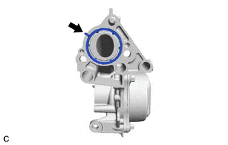
3. REMOVE ENGINE WATER PUMP ASSEMBLY (WATER INLET HOUSING)
| (a) Disconnect the sensor wire connector. |
|
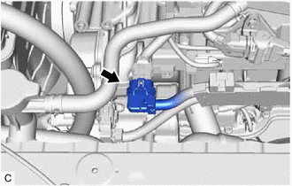
| (b) Using an 8 mm socket wrench, remove the bolt and disconnect the sensor wire from the engine water pump assembly (water inlet housing). |
|
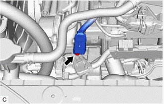
| (c) Disconnect the engine water pump assembly (water inlet housing) connector. |
|
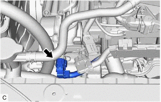
| (d) Remove the 4 bolts and engine water pump assembly (water inlet housing) from the cylinder block assembly. |
|
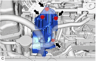
| (e) Remove the gasket from the engine water pump assembly (water inlet housing). |
|