Lexus ES: Components
COMPONENTS
ILLUSTRATION
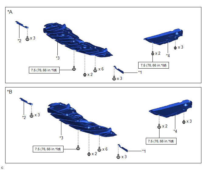
| *A | Type A | *B | Type B |
| *1 | FRONT WHEEL OPENING EXTENSION PAD LH | *2 | FRONT WHEEL OPENING EXTENSION PAD RH |
| *3 | NO. 1 ENGINE UNDER COVER | *4 | NO. 3 ENGINE UNDER COVER |
.png) | N*m (kgf*cm, ft.*lbf): Specified torque | - | - |
ILLUSTRATION
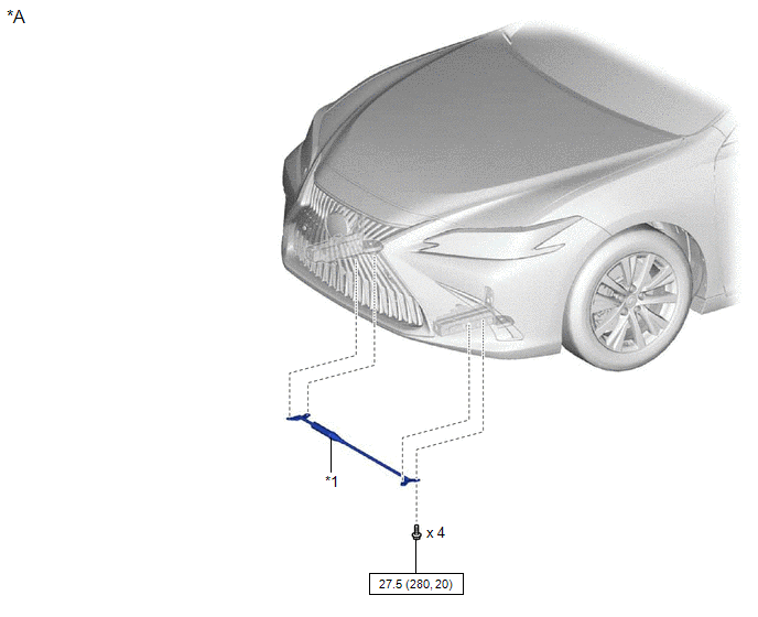
| *A | w/ Performance Damper | - | - |
| *1 | SUSPENSION TOWER DAMPER | - | - |
| | N*m (kgf*cm, ft.*lbf): Specified torque | - | - |
ILLUSTRATION
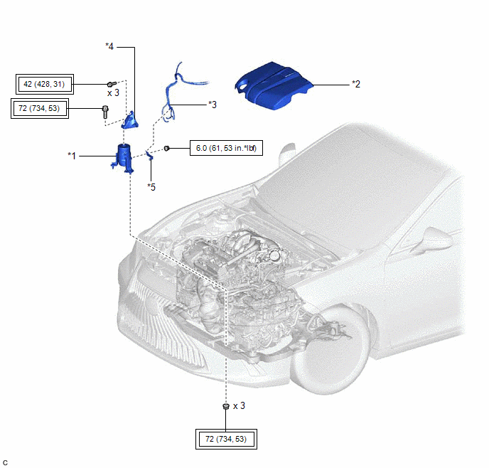
| *1 | FRONT ENGINE MOUNTING INSULATOR | *2 | V-BANK COVER SUB-ASSEMBLY |
| *3 | VACUUM HOSE | *4 | FRONT ENGINE MOUNTING BRACKET |
| *5 | STAY | - | - |
.png) | Tightening torque for "Major areas involving basic vehicle performance such as moving/turning/stopping": N*m (kgf*cm, ft.*lbf) | | N*m (kgf*cm, ft.*lbf): Specified torque |
READ NEXT:
 On-vehicle Inspection
ON-VEHICLE INSPECTION CAUTION / NOTICE / HINT HINT: Refer to Problem Symptoms Table. Click here PROCEDURE 1. REMOVE FRONT WHEEL OPENING EXTENSION PAD LH Click here 2. REMOVE FRONT WHEEL OPENING
Removal
REMOVAL PROCEDURE 1. REMOVE VACUUM SWITCHING VALVE (for Active Control Engine Mount System) Click here 2. REMOVE V-BANK COVER SUB-ASSEMBLY Click here 3. REMOVE FRONT WHEEL OPENING EXTENSION PAD
Installation
INSTALLATION PROCEDURE 1. INSTALL FRONT ENGINE MOUNTING INSULATOR (a) Install the stay to the front engine mounting insulator with the nut. Torque: 6.0 N·m {61 kgf·cm, 53 in·lbf} (b) Install the f
SEE MORE:
How To Proceed With Troubleshooting
CAUTION / NOTICE / HINT HINT:
*: Use the Techstream
Use the following procedure to troubleshoot the motor generator control system.
PROCEDURE 1. VEHICLE BROUGHT TO WORKSHOP
NEXT 2. CUSTOMER PROBLEM ANALYSIS
NEXT 3. CONNECT TECHSTREAM
Components
COMPONENTS ILLUSTRATION *1 CLUTCH DRUM OIL SEAL RING *2 FRONT OIL PUMP BODY *3 FRONT OIL PUMP DRIVE GEAR *4 FRONT OIL PUMP DRIVEN GEAR *5 OIL STRAINER ASSEMBLY *6 RING PIN *7 STATOR SHAFT ASSEMBLY *8 FRONT OIL PUMP COVER SUB-ASSEMBLY Tightening torque f
© 2016-2025 Copyright www.lexguide.net

