Lexus ES: Removal
REMOVAL
PROCEDURE
1. REMOVE NO. 1 INSTRUMENT PANEL UNDER COVER SUB-ASSEMBLY
Click here .gif)
.gif)
2. REMOVE STOP LIGHT SWITCH ASSEMBLY
| (a) Disconnect the connector. | |
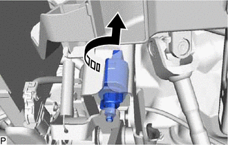
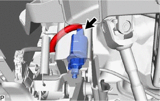
(b) Turn the stop light switch assembly counterclockwise and remove it.

.png) | Remove in this Direction |
READ NEXT:
INSTALLATION PROCEDURE 1. INSTALL STOP LIGHT SWITCH ASSEMBLY (a) Insert the stop light switch assembly until the threaded sleeve hits the pedal as shown in the illustration. *1 Stop Light Switch
COMPONENTS ILLUSTRATION *A for Power Tilt and Power Telescopic Steering Column - - *1 STEERING WHEEL SWITCH HOUSING *2 TILT AND TELESCOPIC SWITCH *3 TURN SIGNAL SWITCH *4
SEE MORE:
SYSTEM DIAGRAM Communication Table Sender Receiver Signal Line Certification ECU (Smart Key ECU Assembly) Main Body ECU (Multiplex Network Body ECU) Luggage compartment door lock assembly open operation signal CAN
ComponentsCOMPONENTS ILLUSTRATION *1 FRONT DRIVE SHAFT OIL SEAL LH - - ● Non-reusable part - - ReplacementREPLACEMENT CAUTION / NOTICE / HINT The necessary procedures (adjustment, calibration, initialization or registration) that must be performed after parts are removed a
© 2016-2025 Copyright www.lexguide.net


.gif)
.gif)

.png)


