Lexus ES: Removal
REMOVAL
CAUTION / NOTICE / HINT
The necessary procedures (adjustment, calibration, initialization or registration) that must be performed after parts are removed and installed, or replaced during steering wheel assembly removal/installation are shown below.
Necessary Procedures After Parts Removed/Installed/Replaced (for Gasoline Model)| Replaced Part or Performed Procedure | Necessary Procedure | Effect/Inoperative Function when Necessary Procedure not Performed | Link |
|---|---|---|---|
|
*: When performing learning using the Techstream.
Click here | |||
| Disconnect cable from negative auxiliary battery terminal | Perform steering sensor zero point calibration | Lane Control System | |
| Pre-collision System | |||
| Parking Support Brake System* | |||
| Lighting System | |||
| Memorize steering angle neutral point | Parking Assist Monitor System | | |
| Panoramic View Monitor System | | ||
| Initialize power trunk lid system | Power Trunk Lid System | | |
| Replaced Part or Performed Procedure | Necessary Procedure | Effect/Inoperative Function when Necessary Procedure not Performed | Link |
|---|---|---|---|
|
*: When performing learning using the Techstream.
Click here | |||
| Disconnect cable from negative auxiliary battery terminal | Perform steering sensor zero point calibration | Lane Control System | |
| Pre-collision System | |||
| Parking Support Brake System* | |||
| Lighting System | |||
| Memorize steering angle neutral point | Parking Assist Monitor System | | |
| Panoramic View Monitor System | | ||
| Initialize power trunk lid system | Power Trunk Lid System | | |
NOTICE:
- Do not remove/install the spiral cable with sensor sub-assembly with the auxiliary battery connected and the engine switch (for Gasoline Model) or power switch (for HV Model) on (IG).
- Do not rotate the spiral cable with sensor sub-assembly without the steering wheel assembly installed, with the auxiliary battery connected and the engine switch (for Gasoline Model) or power switch (for HV Model) on (IG).
- Ensure that the steering wheel assembly is installed and aligned straight when inspecting the steering sensor.
- After the engine switch is turned off, the radio receiver assembly records various types of memory and settings. As a result, after turning the engine switch off, make sure to wait at least 85 seconds before disconnecting the cable from the negative (-) battery terminal. (for Audio and Visual System)
- After the engine switch is turned off, the radio receiver assembly records various types of memory and settings. As a result, after turning the engine switch off, make sure to wait at least 85 seconds before disconnecting the cable from the negative (-) battery terminal. (for Navigation System)
- After the power switch is turned off, the radio receiver assembly records various types of memory and settings. As a result, after turning the power switch off, make sure to wait at least 85 seconds before disconnecting the cable from the negative (-) auxiliary battery terminal. (for Audio and Visual System)
- After the power switch is turned off, the radio receiver assembly records various types of memory and settings. As a result, after turning the power switch off, make sure to wait at least 85 seconds before disconnecting the cable from the negative (-) auxiliary battery terminal. (for Navigation System)
PROCEDURE
1. ALIGN FRONT WHEELS FACING STRAIGHT AHEAD
2. REMOVE HORN BUTTON ASSEMBLY
Click here .gif)
3. REMOVE STEERING WHEEL ASSEMBLY
(a) Disconnect each connector from the spiral cable with sensor sub-assembly and steering wheel assembly.
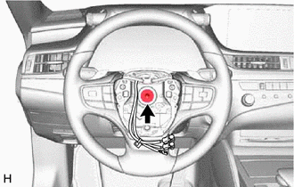
| (b) Using a 10 mm hexagon socket wrench, remove the steering wheel assembly set bolt. |
|
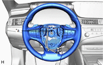
| (c) Put matchmarks on the steering wheel assembly and steering main shaft. |
|
(d) Temporarily install the steering wheel assembly set bolt.
NOTICE:
Do not overtighten the steering wheel assembly set bolt.
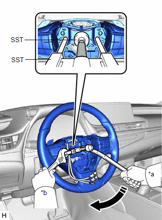
| (e) Using SST, separate the steering wheel assembly. SST: 09950-50013 09951-05010 09952-05010 09953-05020 09954-05031 09957-04010 SST: 09950-60010 09951-00330 NOTICE: Apply a small amount of grease to the threads and tip of SST (09953-05020) before use. |
|
(f) Remove the steering wheel assembly set bolt and steering wheel assembly.
4. REMOVE HEATED STEERING WHEEL CONTROLLER (STEERING VIBRATION ECU)
Click here .gif)
5. REMOVE STEERING PAD SWITCH ASSEMBLY
Click here .gif)
6. REMOVE NO. 1 STEERING WHEEL ORNAMENT
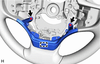
| (a) Remove the 2 screws and disengage the pin to remove the No. 1 steering wheel ornament. |
|
7. REMOVE SHIFT PADDLE SWITCH (TRANSMISSION SHIFT SWITCH ASSEMBLY)
for Gasoline Model: Click here .gif)
for HV Model: Click here .gif)
8. REMOVE NO. 1 SWITCH WIRE
for Gasoline Model: Click here .gif)
for HV Model: Click here .gif)


