Lexus ES manuals

Lexus ES: Removal

REMOVAL

CAUTION / NOTICE / HINT

The necessary procedures (adjustment, calibration, initialization, or registration) that must be performed after parts are removed and installed, or replaced during side television camera assembly removal/installation are shown below.

Necessary Procedure After Parts Removed/Installed/Replaced (for HV Model)

Replaced Part or Performed Procedure

Necessary Procedure

Effect/Inoperative Function When Necessary Procedures are not Performed

Link

  • Side television camera assembly LH
  • Side television camera assembly RH

Side television camera view adjustment

Panoramic View Monitor System

Necessary Procedure After Parts Removed/Installed/Replaced (for Gasoline Model)

Replaced Part or Performed Procedure

Necessary Procedure

Effect/Inoperative Function When Necessary Procedures are not Performed

Link

  • Side television camera assembly LH
  • Side television camera assembly RH

Side television camera view adjustment

Panoramic View Monitor System

HINT:

  • Use the same procedure for the RH side and LH side.
  • The following procedure is for the LH side.

PROCEDURE

1. REMOVE OUTER MIRROR

Click here

2. REMOVE OUTER MIRROR COVER ASSEMBLY

Click here

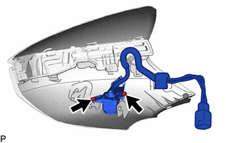
3. REMOVE SIDE TELEVISION CAMERA ASSEMBLY

(a) Remove the 2 screws and side television camera assembly.

READ NEXT:

 Television Camera(for Rear)

 Components

COMPONENTS ILLUSTRATION *1 REAR TELEVISION CAMERA ASSEMBLY *2 TELEVISION CAMERA ASSEMBLY WITH WIRE *3 TELEVISION CAMERA WIRE - -

 Installation

INSTALLATION PROCEDURE 1. INSTALL REAR TELEVISION CAMERA ASSEMBLY 2. INSTALL TELEVISION CAMERA WIRE (a) Connect the connector to install the television camera wire. 3. INSTALL TELEVISION CAMERA ASSEMB

SEE MORE:

 Drive Motor "A" Inverter Actuator Stuck Open (P0A7872)

DTC SUMMARY MALFUNCTION DESCRIPTION This DTC is stored when the motor generator control system is malfunctioning and current does not flow as commanded. The cause of this malfunction may be one of the following: Internal inverter malfunction Inverter with converter assembly internal circuit malfu

 Parts Location

PARTS LOCATION ILLUSTRATION *1 MILLIMETER WAVE RADAR SENSOR ASSEMBLY *2 FORWARD RECOGNITION CAMERA *3 BRAKE BOOSTER WITH MASTER CYLINDER ASSEMBLY - SKID CONTROL ECU *4 BRAKE ACTUATOR ASSEMBLY - PARKING BRAKE ECU ILLUSTRATION *1 STOP LIGHT SWITCH ASSEMBLY *2 SPIRAL CA

© 2016-2025 Copyright www.lexguide.net