Lexus ES: Parts Location
PARTS LOCATION
ILLUSTRATION
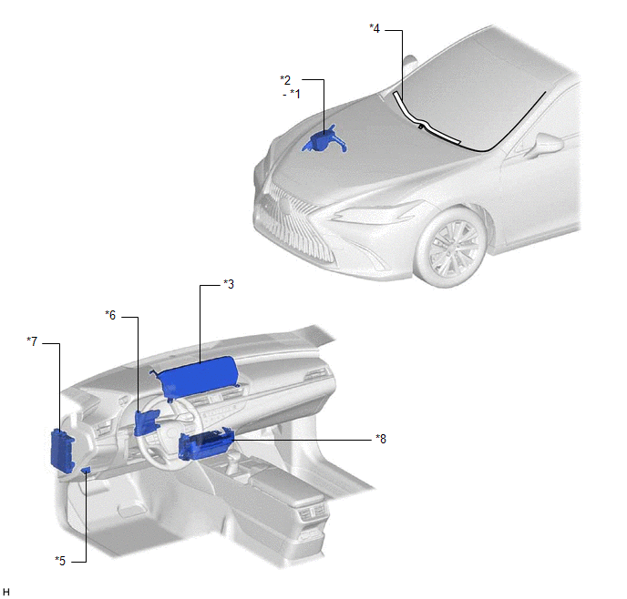
| *1 | DEICER RELAY | *2 | NO. 2 ENGINE ROOM RELAY BLOCK AND NO. 2 ENGINE ROOM JUNCTION BLOCK ASSEMBLY - DEICER FUSE |
| *3 | MULTI-DISPLAY ASSEMBLY - FRONT WIPER DEICER SWITCH | *4 | WINDSHIELD DEICER WIRE (WINDSHIELD GLASS) |
| *5 | DLC3 | *6 | AIR CONDITIONING AMPLIFIER ASSEMBLY |
| *7 | INSTRUMENT PANEL JUNCTION BLOCKASSEMBLY - ECU-IG2 NO. 3 FUSE | *8 | RADIO RECEIVER ASSEMBLY |
READ NEXT:
 System Diagram
SYSTEM DIAGRAM Sender Receiver Signal Communication Method Radio Receiver Assembly Air Conditioning Amplifier Assembly Front wiper deicer switch signal CAN
System Description
SYSTEM DESCRIPTION GENERAL The windshield deicer system uses thin heater wires attached to the inside of the windshield glass to help deice the window surface more quickly. An indicator light illumina
How To Proceed With Troubleshooting
CAUTION / NOTICE / HINT HINT:
Use the following procedure to troubleshoot the windshield deicer system.
*: Use the Techstream.
PROCEDURE 1. VEHICLE BROUGHT TO WORKSHOP
NEXT
SEE MORE:
AUTO Power Retract Mirrors do not operate
DESCRIPTION The outer mirror switch assembly sends the retractable outer mirror switch signal to the main body ECU (multiplex network body ECU). The main body ECU (multiplex network body ECU) sends the auto retract/return signal to the outer mirror control ECU assemblies via CAN communication, which
Voice Guidance Circuit between Radio Receiver and Stereo Component Amplifier
DESCRIPTION Using this circuit, the radio receiver assembly sends signals to the stereo component amplifier assembly. WIRING DIAGRAM PROCEDURE 1. CHECK HARNESS AND CONNECTOR (RADIO RECEIVER ASSEMBLY - STEREO COMPONENT AMPLIFIER ASSEMBLY) (a) Disconnect the G7 radio receiver assembly connec
© 2016-2025 Copyright www.lexguide.net

