Lexus ES: Installation
INSTALLATION
PROCEDURE
1. INSTALL LEAK DETECTION PUMP SUB-ASSEMBLY
HINT:
Only perform this procedure when replacement of the leak detection pump sub-assembly is necessary.
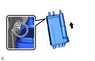
| (a) Engage the 2 claws to install a new leak detection pump sub-assembly to the No. 2 charcoal canister sub-assembly. NOTICE:
|
|
.png)
2. INSTALL NO. 2 CHARCOAL CANISTER SUB-ASSEMBLY
(a) Install the No. 2 charcoal canister sub-assembly to the vehicle body with the 3 nuts.
Torque:
8.0 N·m {82 kgf·cm, 71 in·lbf}
(b) Connect the leak detection pump sub-assembly connector.
(c) Push the air line tube onto the (leak detection pump sub-assembly) and push in the retainer to engage the lock claws.
NOTICE:
- Check that there are no scratches or foreign matter around the connecting parts of the tube connector and pipe (leak detection pump sub-assembly) before performing this work.
- After connecting the air line tube, check that the air line tube is securely connected by pulling on the tube connector.
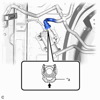
| *a | Retainer |
.png) | Push in |
(d) Engage the 2 clamps.
3. INSTALL CANISTER (CHARCOAL CANISTER ASSEMBLY)
(a) Install the clip to the vehicle body.
| (b) Engage the claw to install the canister (charcoal canister assembly) to the vehicle body as shown in the illustration. |
|
(c) Engage the clip to the canister (charcoal canister assembly).
(d) Install the 2 bolts.
Torque:
8.0 N·m {82 kgf·cm, 71 in·lbf}
(e) Connect the purge line hose to the canister (charcoal canister assembly) and slide the clip to secure it.
(f) Push the vent line hose onto the canister (charcoal canister assembly) and push in the retainer to engage the lock claws.
NOTICE:
- Check that there are no scratches or foreign matter around the connecting parts of the tube connector and pipe (canister (charcoal canister assembly)) before performing this work.
- After connecting the vent line hose, check that the vent line hose is securely connected by pulling on the tube connector.
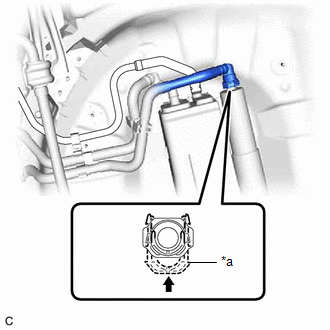
| *a | Retainer |
| | Push in |
(g) Push the fuel tank vent hose onto the canister (charcoal canister assembly) and push in the retainer to engage the lock claws.
NOTICE:
- Check that there are no scratches or foreign matter around the connecting parts of the tube connector and pipe (canister (charcoal canister assembly)) before performing this work.
- After connecting the fuel tank vent hose, check that the fuel tank vent hose is securely connected by pulling on the tube connector.
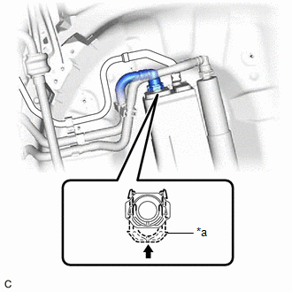
| *a | Retainer |
| | Push in |
4. INSTALL REAR FLOOR SIDE MEMBER COVER
| (a) Engage the 3 clamps (A) and 2 clamps (B) to install the rear floor side member cover to the vehicle body. |
|
.png)
(b) Install the bolt and 7 clips.
Torque:
Bolt :
7.5 N·m {76 kgf·cm, 66 in·lbf}
