Lexus ES: Reassembly
REASSEMBLY
PROCEDURE
1. INSTALL STARTER CENTER BEARING CLUTCH SUB-ASSEMBLY
(a) Apply high-temperature grease to the pinion drive lever.
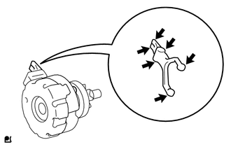
.png) | High-temperature Grease |
HINT:
Apply approximately 0.1 g of high-temperature grease to each section.
| (b) Align the cutout of the starter drive housing assembly with the protrusion of the starter center bearing clutch sub-assembly and install the starter center bearing clutch sub-assembly. |
|
| (c) Install the rubber seal to the starter drive housing assembly. |
|
.png)
2. INSTALL STARTER BRUSH HOLDER ASSEMBLY
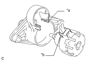
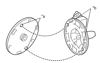
| (a) Install the starter commutator end frame assembly to the starter brush holder assembly as shown in the illustration. HINT: If the parts are not aligned correctly, the through bolt cannot be attached. |
|
| (b) Spread the brushes on the starter brush holder assembly, and install the starter armature assembly to the starter brush holder assembly. |
|
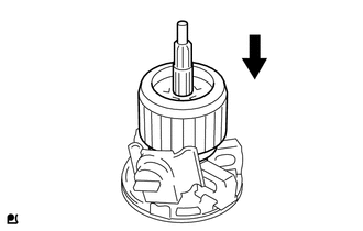
3. INSTALL STARTER ARMATURE ASSEMBLY
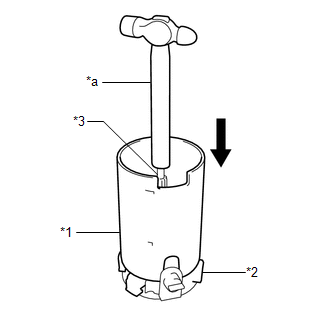
| (a) Install the starter yoke assembly while holding down the starter armature assembly and starter brush holder assembly with the handle of a hammer. HINT: The starter armature assembly will be attracted by the magnetic field of the starter yoke assembly. Hold the starter armature assembly with the handle of the hammer. |
|
4. INSTALL STARTER YOKE ASSEMBLY
| (a) Align the cutout of the starter yoke assembly with the protrusion of the starter center bearing clutch sub-assembly. |
|
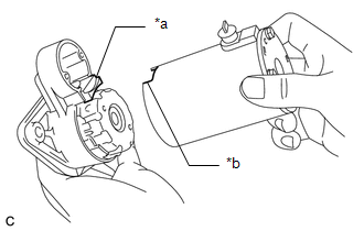
| (b) Install the starter yoke assembly with the 3 through bolts. Torque: 3.0 N·m {31 kgf·cm, 27 in·lbf} |
|
.png)
5. INSTALL MAGNET STARTER SWITCH ASSEMBLY
| (a) Hang the hook of the magnet starter switch assembly on the pinion drive lever. |
|
.png)
| (b) Push down the rear of the magnet starter switch assembly and connect it to terminal C. NOTICE:
|
|
.png)
| (c) Install the magnet starter switch assembly with the 2 bolts. Torque: 3.0 N·m {31 kgf·cm, 27 in·lbf} |
|
.png)
