Lexus ES: Parts Location
PARTS LOCATION
ILLUSTRATION
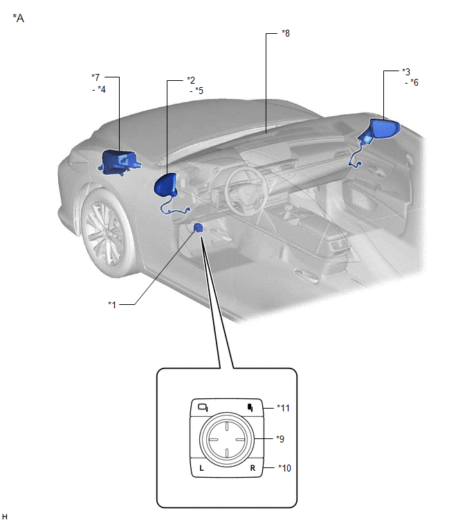
| *1 | OUTER MIRROR SWITCH ASSEMBLY | *2 | OUTER REAR VIEW MIRROR ASSEMBLY LH |
| *3 | OUTER REAR VIEW MIRROR ASSEMBLY RH | *4 | DEF RELAY |
| *5 | OUTER MIRROR LH | *6 | OUTER MIRROR RH |
| *7 | NO. 1 ENGINE ROOM RELAY BLOCK AND NO. 1 JUNCTION BLOCK ASSEMBLY - DEF FUSE - MIR HTR FUSE | *8 | INNER REAR VIEW MIRROR ASSEMBLY |
| *9 | MIRROR ADJUST SWITCH | *10 | MIRROR SELECT SWITCH |
ILLUSTRATION
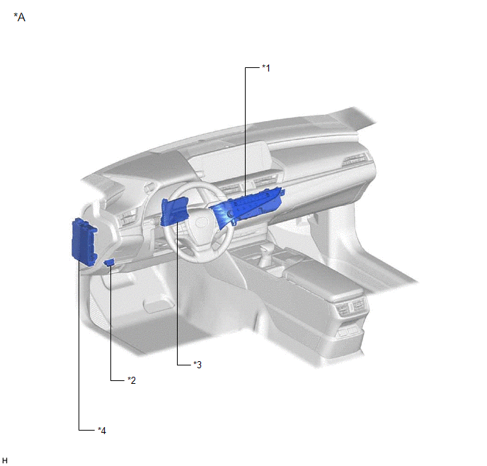
| *1 | REAR WINDOW DEFOGGER SWITCH (AIR CONDITIONING CONTROL ASSEMBLY) | *2 | DLC3 |
| *3 | AIR CONDITIONING AMPLIFIER ASSEMBLY | *4 | INSTRUMENT PANEL JUNCTION BLOCK ASSEMBLY - ECU-ACC FUSE - ECU-IG1 NO. 3 FUSE |
READ NEXT:
 System Diagram
SYSTEM DIAGRAM ELECTRICAL REMOTE CONTROL MIRROR FUNCTION MIRROR HEATER FUNCTION AUTOMATIC GLARE-RESISTANT EC MIRROR FUNCTION Communication Table Sender Receiver Signal Communication Metho
System Description
SYSTEM DESCRIPTION POWER MIRROR CONTROL SYSTEM (w/o Memory) DESCRIPTION (a) This system has the following functions: electrical remote control mirror function, power retract mirror function, mirror he
How To Proceed With Troubleshooting
CAUTION / NOTICE / HINT HINT:
Use the following procedure to troubleshoot the power mirror control system (w/o Memory).
*: Use the Techstream.
PROCEDURE 1. VEHICLE BROUGHT TO WORKSHOP
SEE MORE:
Parts Location
PARTS LOCATION ILLUSTRATION *1 FRONT TELEVISION CAMERA ASSEMBLY *2 SIDE TELEVISION CAMERA ASSEMBLY RH *3 SIDE TELEVISION CAMERA ASSEMBLY LH *4 BRAKE BOOSTER WITH MASTER CYLINDER ASSEMBLY - SKID CONTROL ECU *5 SHIFT LEVER POSITION SENSOR *6 REAR TELEVISION CAMERA ASSEMBL
Removal
REMOVAL CAUTION / NOTICE / HINT The necessary procedures (adjustment, calibration, initialization, or registration) that must be performed after parts are removed and installed, or replaced during telephone antenna assembly removal/installation are shown below. Necessary Procedure After Parts Remove
© 2016-2025 Copyright www.lexguide.net

