Lexus ES: Installation
INSTALLATION
PROCEDURE
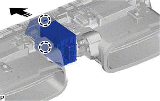
1. INSTALL HAZARD WARNING SIGNAL SWITCH ASSEMBLY
(a) Engage the 2 claws to install the hazard warning signal switch assembly.

.png) | Install in this Direction |
2. INSTALL NO. 2 INSTRUMENT PANEL REGISTER ASSEMBLY
Click here .gif)
3. INSTALL UPPER INSTRUMENT PANEL FINISH PANEL SUB-ASSEMBLY
Click here .gif)
4. INSTALL INSTRUMENT CLUSTER FINISH PANEL SUB-ASSEMBLY (w/o Headup Display)
Click here .gif)
5. INSTALL INSTRUMENT CLUSTER FINISH PANEL SUB-ASSEMBLY (w/ Headup Display)
Click here .gif)
6. INSTALL NO. 1 INSTRUMENT CLUSTER MOULDING
Click here .gif)
7. INSTALL LOWER INSTRUMENT PANEL FINISH PANEL SUB-ASSEMBLY
Click here .gif)
8. INSTALL NO. 1 INSTRUMENT PANEL UNDER COVER SUB-ASSEMBLY
Click here .gif)
9. INSTALL INSTRUMENT SIDE PANEL LH
Click here .gif)
10. INSTALL FRONT DOOR OPENING TRIM COVER LH
Click here .gif)
11. INSTALL COWL SIDE TRIM BOARD LH
Click here .gif)
12. INSTALL FRONT DOOR SCUFF PLATE LH
Click here .gif)
13. INSTALL AIR CONDITIONING CONTROL ASSEMBLY
Click here .gif)

