Lexus ES: Installation
INSTALLATION
CAUTION / NOTICE / HINT
HINT:
- Use the same procedure for the RH side and LH side.
- The following procedure is for the LH side.
PROCEDURE
1. INSTALL NO. 3 WINDSHIELD OUTSIDE MOULDING CLIP
HINT:
Perform the following procedure only when replacement of a No. 3 windshield outside moulding clip is necessary.
(a) Using a riveter with a nose piece, install 5 new No. 3 windshield outside moulding clips.
HINT:
If the mandrel of the No. 3 windshield outside moulding clip does not come off on the first operation of the rivet gun, slide the rivet gun forward on the mandrel and operate it again.
NOTICE:
- Do not pry the No. 3 windshield outside moulding clip with the riveter, as this will cause damage to the riveter and mandrel.
-
Confirm that the No. 3 windshield outside moulding clips are seated properly against the vehicle body.
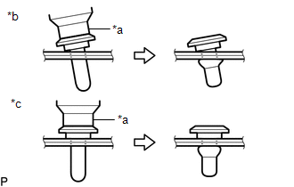
*a
Riveter
*b
Incorrect
*c
Correct
- Do not tilt the riveter when installing the No. 3 windshield outside moulding clip to the vehicle body.

| *a | Riveter |
| *b | Mandrel |
| *c | Incorrect |

(b) Install the windshield glass sub-assembly.
Click here .gif)
2. INSTALL NO. 1 WINDSHIELD OUTSIDE MOULDING CLIP
HINT:
Perform the following procedure only when replacement of a No. 1 windshield outside moulding clip is necessary.
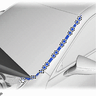
(a) Engage the 5 claws to install the 5 No. 1 windshield outside moulding clips as shown in the illustration.

.png) | Install in this Direction | - | - |
3. INSTALL WINDSHIELD OUTSIDE MOULDING
| (a) Engage the 11 claws and 2 guides to install the windshield outside moulding. |
|