Lexus ES manuals

Lexus ES: Installation

INSTALLATION

PROCEDURE

1. INSTALL REAR BUMPER ASSEMBLY

(a) w/ Wire Harness:

(1) Connect the connector.

(b) Engage the 6 claws as shown in the illustration.
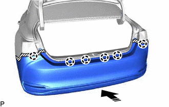
Install in this Direction

(c) Engage the 6 claws as shown in the illustration.

Install in this Direction

HINT:

Use the same procedure for the RH side and LH side.

(d) Install the 12 clips.

(e) Install the screw.

HINT:

Use the same procedure for the RH side and LH side.

(f) Engage the 2 claws.

HINT:

Use the same procedure for the RH side and LH side.

(g) Install the clip.

HINT:

Use the same procedure for the RH side and LH side.

(h) Install the rear bumper assembly with the 2 screws.

2. INSTALL REAR COMBINATION LIGHT COVER LH

Click here

3. INSTALL REAR COMBINATION LIGHT COVER RH

HINT:

Use the same procedure as for the LH side.

4. CONNECT CABLE TO NEGATIVE AUXILIARY BATTERY TERMINAL (w/ Hands Free Power Trunk Lid)

Click here

5. INITIALIZE KICK DOOR CONTROL SENSOR (w/ Hands Free Power Trunk Lid)

Click here

6. INSPECT KICK DOOR CONTROL SENSOR (w/ Hands Free Power Trunk Lid)

Click here

7. PERFORM CALIBRATION (w/ Parking Support Brake System)

Click here

READ NEXT:

 Rear Door Belt Moulding

 Components

COMPONENTS ILLUSTRATION *1 COURTESY LIGHT ASSEMBLY *2 REAR DOOR TRIM BOARD SUB-ASSEMBLY *3 REAR DOOR UPPER TRIM PAD *4 REAR POWER WINDOW REGULATOR SWITCH ASSEMBLY WITH REAR DOOR UP

 Removal

REMOVAL CAUTION / NOTICE / HINT The necessary procedures (adjustment, calibration, initialization, or registration) that must be performed after parts are removed and installed, or replaced during rea

SEE MORE:

 The Display of the Multi-display does not Switched

DESCRIPTION The multi-display receives a signal from the clearance warning ECU assembly to change the display screen. WIRING DIAGRAM PROCEDURE 1. CHECK HARNESS AND CONNECTOR (CLEARANCE WARNING ECU ASSEMBLY - MULTI-DISPLAY ASSEMBLY) (a) Disconnect the N41 clearance warning ECU assembly conn

 Removal

REMOVAL CAUTION / NOTICE / HINT The necessary procedures (adjustment, calibration, initialization, or registration) that must be performed after parts are removed, installed, or replaced during brake pedal stroke sensor assembly removal/installation are shown below. Necessary Procedures After Parts

© 2016-2025 Copyright www.lexguide.net