Lexus ES: Inspection
INSPECTION
PROCEDURE
1. INSPECT POWER WINDOW REGULATOR MOTOR ASSEMBLY (FOR REAR LH DOOR)
| (a) Connect a positive (+) lead from the auxiliary battery to connector terminal 2. NOTICE: Do not connect a positive (+) lead from the auxiliary battery to any terminal other than terminal 2 to avoid damaging the pulse sensor inside the motor. | 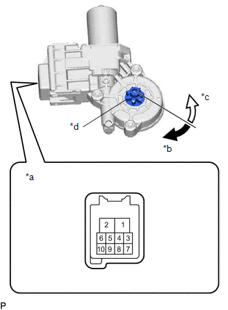 | | *a | Component without harness connected (Power Window Regulator Motor Assembly (for Rear LH Door)) | | *b | Clockwise | | *c | Counterclockwise | | *d | Motor gear | | |
(b) Connect a negative (-) lead from the auxiliary battery to connector terminals 1 and 7 or 10.
(c) Check that the motor gear rotates smoothly as follows:
OK:
| Measurement Condition | Specified Condition |
-
Connect a positive (+) lead from the auxiliary battery to terminal 2, connect a negative (-) lead from the auxiliary battery to terminal 1, and keep them connected for 3 seconds or more.
-
With terminals 2 and 1 connected, connect a negative (-) lead from the auxiliary battery to terminal 10.
| Motor gear rotates clockwise |
-
Connect a positive (+) lead from the auxiliary battery to terminal 2, connect a negative (-) lead from the auxiliary battery to terminal 1, and keep them connected for 3 seconds or more.
-
With terminals 2 and 1 connected, connect a negative (-) lead from the auxiliary battery to terminal 7.
| Motor gear rotates counterclockwise |
-
If the result is not as specified, replace the power window regulator motor assembly (for rear LH door).
CAUTION:
Initialize the power window control system after installing the rear door window regulator assembly.
2. INSPECT POWER WINDOW REGULATOR MOTOR ASSEMBLY (FOR REAR RH DOOR)
| (a) Connect a positive (+) lead from the auxiliary battery to connector terminal 2. NOTICE: Do not connect a positive (+) lead from the auxiliary battery to any terminal other than terminal 2 to avoid damaging the pulse sensor inside the motor. | 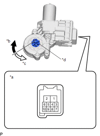 | | *a | Component without harness connected (Power Window Regulator Motor Assembly (for Rear RH Door)) | | *b | Clockwise | | *c | Counterclockwise | | *d | Motor gear | | |
(b) Connect a negative (-) lead from the auxiliary battery to connector terminals 1 and 7 or 10.
(c) Check that the motor gear rotates smoothly as follows:
OK:
| Measurement Condition | Specified Condition |
-
Connect the positive (+) lead from the auxiliary battery to terminal 2, connect a negative (-) lead from the auxiliary battery to terminal 1, and keep them connected for 3 seconds or more.
-
With terminals 2 and 1 connected, connect a negative (-) lead from the auxiliary battery to terminal 10.
| Motor gear rotates counterclockwise |
-
Connect a positive (+) lead from the auxiliary battery to terminal 2, connect a negative (-) lead from the auxiliary battery to terminal 1, and keep them connected for 3 seconds or more.
-
With terminals 2 and 1 connected, connect a negative (-) lead from the auxiliary battery to terminal 7.
| Motor gear rotates clockwise |
-
If the result is not as specified, replace the power window regulator motor assembly (for rear RH door).
CAUTION:
Initialize the power window control system after installing the rear door window regulator assembly.
READ NEXT:
INSTALLATION CAUTION / NOTICE / HINT HINT:
Use the same procedure for the RH side and LH side.
The following procedure is for the LH side.
PROCEDURE 1. PRECAUTION NOTICE: After turning the eng
ComponentsCOMPONENTS ILLUSTRATION *1 REAR POWER WINDOW REGULATOR SWITCH ASSEMBLY *2 REAR POWER WINDOW REGULATOR SWITCH ASSEMBLY WITH REAR DOOR UPPER ARMREST BASE PANEL RemovalREMOVAL CA
On-vehicle InspectionON-VEHICLE INSPECTION PROCEDURE 1. INSPECT DEF RELAY (a) Measure the resistance according to the value(s) in the table below. Standard Resistance: Tester Connection Cond
SEE MORE:
DTC CHECK / CLEAR CHECK DTCs (USING TECHSTREAM) (a) Turn the engine switch off. (b) Connect the Techstream to the DLC3. (c) Turn the engine switch on (IG). (d) Turn the Techstream on. (e) Enter the following menus: Chassis / EMPS / Trouble Codes. Chassis > EMPS > Trouble Codes (f) Check the de
PARTS LOCATION ILLUSTRATION *1 HYBRID VEHICLE CONTROL ECU *2 REAR TELEVISION CAMERA ASSEMBLY *3 BLIND SPOT MONITOR SENSOR RH (w/ Blind Spot Monitor System) *4 BLIND SPOT MONITOR SENSOR LH (w/ Blind Spot Monitor System) ILLUSTRATION *1 MAIN BODY ECU (MULTIPLEX NETWORK BOD
© 2016-2025 Copyright www.lexguide.net


