Lexus ES: Disassembly
DISASSEMBLY
PROCEDURE
1. REMOVE CLUTCH DRUM OIL SEAL RING
| (a) Remove the 4 clutch drum oil seal rings from the stator shaft assembly. | |
2. REMOVE OIL STRAINER ASSEMBLY
| (a) Using a T30 "TORX" socket wrench, remove the 2 bolts and oil strainer assembly from the front oil pump cover sub-assembly. | |
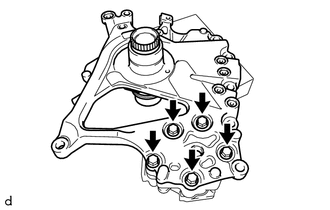
3. REMOVE STATOR SHAFT ASSEMBLY
| (a) Remove the 5 bolts and stator shaft assembly from the front oil pump body. | |
4. REMOVE FRONT OIL PUMP DRIVE GEAR
| (a) Remove the front oil pump drive gear from the front oil pump body. | |
5. REMOVE FRONT OIL PUMP DRIVEN GEAR
| (a) Remove the front oil pump driven gear from the front oil pump body. | |
6. REMOVE FRONT OIL PUMP BODY
| (a) Remove the front oil pump body from the front oil pump cover sub-assembly. | |
7. REMOVE RING PIN
| (a) Remove the 2 ring pins from the front oil pump cover sub-assembly. | |
READ NEXT:
INSPECTION PROCEDURE 1. INSPECT FRONT OIL PUMP ASSEMBLY (a) Install the oil pump drive shaft sub-assembly to the front oil pump assembly. NOTICE:
To avoid damaging the bush of the front oil pu
REASSEMBLY PROCEDURE 1. INSTALL RING PIN (a) Install the 2 ring pins to the front oil pump cover sub-assembly. 2. INSTALL FRONT OIL PUMP BODY (a) Install the front oil pump body to t
SEE MORE:
DTC CHECK / CLEAR CHECK DTC (a) Connect the Techstream to the DLC3. (b) Turn the power switch on (IG). (c) Turn the Techstream on. (d) Enter the following menus: Body Electrical / Telematics / Trouble Codes. Body Electrical > Telematics > Trouble Codes (e) Check for DTCs. Click here CLEAR DT
RELATED DTCS DTC No. SAE Monitoring Item Link P00FE00 P00FE EVAP vent line blocked P043E00 P043E Reference orifice clogged (built into canister pump module) P043F00 P043F Reference orifice high-flow (built into canister pump module) P04417E P0441 Pu
© 2016-2025 Copyright www.lexguide.net