Lexus ES: Components
COMPONENTS
ILLUSTRATION
.png)
| *1 | CENTER INSTRUMENT CLUSTER FINISH PANEL SUB-ASSEMBLY | *2 | INSTRUMENT PANEL FINISH PANEL END LH |
| *3 | INSTRUMENT PANEL FINISH PANEL END RH | *4 | REAR UPPER CONSOLE PANEL SUB-ASSEMBLY |
| *5 | SHIFT LEVER KNOB SUB-ASSEMBLY | *6 | UPPER CONSOLE PANEL SUB-ASSEMBLY |
ILLUSTRATION
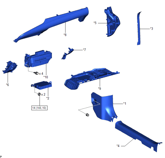
| *1 | COWL SIDE TRIM BOARD RH | *2 | DCM (TELEMATICS TRANSCEIVER) WITH BRACKET |
| *3 | FRONT DOOR OPENING TRIM COVER RH | *4 | FRONT DOOR SCUFF PLATE RH |
| *5 | INSTRUMENT SIDE PANEL RH | *6 | LOWER INSTRUMENT PANEL |
| *7 | LOWER INSTRUMENT PANEL LH | *8 | LOWER INSTRUMENT PANEL SUB-ASSEMBLY |
| *9 | NO. 2 INSTRUMENT PANEL UNDER COVER SUB-ASSEMBLY | *10 | RADIO RECEIVER ASSEMBLY WITH SWITCH |
.png) | N*m (kgf*cm, ft.*lbf) : Specified torque | - | - |
ILLUSTRATION
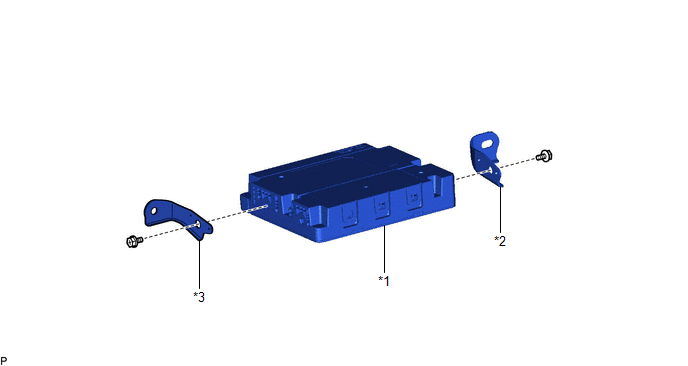
| *1 | DCM (TELEMATICS TRANSCEIVER) | *2 | NO. 1 TELEPHONE BRACKET |
| *3 | TELEPHONE BRACKET | - | - |
READ NEXT:
 Installation
INSTALLATION PROCEDURE 1. INSTALL DCM (TELEMATICS TRANSCEIVER) 2. INSTALL NO. 1 TELEPHONE BRACKET (a) Install the No. 1 telephone bracket with the screw. 3. INSTALL TELEPHONE BRACKET (a) Install the t
Installation
INSTALLATION PROCEDURE 1. INSTALL DCM (TELEMATICS TRANSCEIVER) 2. INSTALL NO. 1 TELEPHONE BRACKET (a) Install the No. 1 telephone bracket with the screw. 3. INSTALL TELEPHONE BRACKET (a) Install the t
Removal
REMOVAL CAUTION / NOTICE / HINT The necessary procedures (adjustment, calibration, initialization, or registration) that must be performed after parts are removed and installed, or replaced during DCM
SEE MORE:
How To Proceed With Troubleshooting
CAUTION / NOTICE / HINT HINT:
Use the following procedure to troubleshoot the power mirror control system (w/ Memory).
*: Use the Techstream.
PROCEDURE 1. VEHICLE BROUGHT TO WORKSHOP
NEXT 2. CUSTOMER PROBLEM ANALYSIS HINT:
In troubleshooting, confirm tha
How To Proceed With Troubleshooting
CAUTION / NOTICE / HINT HINT:
Use the following procedure to troubleshoot the fuel lid opener system.
*: Use the GTS.
PROCEDURE 1. VEHICLE BROUGHT TO WORKSHOP
NEXT 2. CUSTOMER PROBLEM ANALYSIS HINT:
In troubleshooting, confirm that the problem symptoms h
© 2016-2025 Copyright www.lexguide.net

