Lexus ES: Components
COMPONENTS
ILLUSTRATION
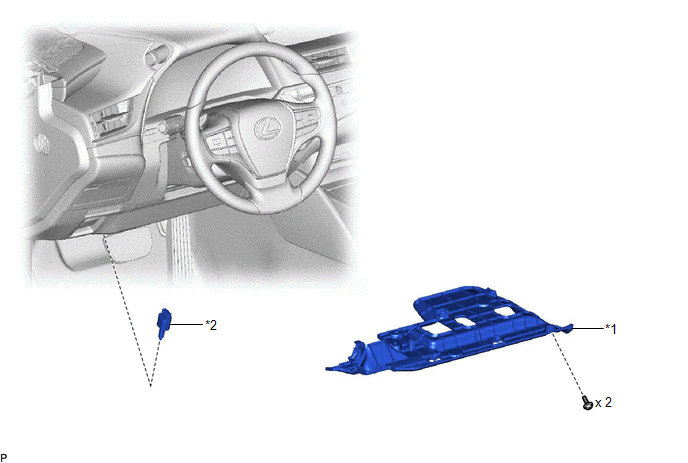
| *1 | NO. 1 INSTRUMENT PANEL UNDER COVER SUB-ASSEMBLY | *2 | STOP LIGHT SWITCH ASSEMBLY |
READ NEXT:
 On-vehicle Inspection
ON-VEHICLE INSPECTION PROCEDURE 1. INSPECT STOP LIGHT SWITCH ASSEMBLY (a) Disconnect the A80 stop light switch assembly connector. *a Front view of wire harness connector (to Stop Li
Removal
REMOVAL PROCEDURE 1. REMOVE NO. 1 INSTRUMENT PANEL UNDER COVER SUB-ASSEMBLY Click here 2. REMOVE STOP LIGHT SWITCH ASSEMBLY (a) Disconnect the connector. (b) Turn the stop light swit
Installation
INSTALLATION PROCEDURE 1. INSTALL STOP LIGHT SWITCH ASSEMBLY (a) Insert the stop light switch assembly until the threaded sleeve hits the pedal as shown in the illustration. *1 Stop Light Switch
SEE MORE:
Precaution
PRECAUTION PRECAUTION FOR DISCONNECTING CABLE FROM NEGATIVE BATTERY TERMINAL NOTICE:
When disconnecting the cable from the negative (-) battery terminal, initialize the following systems after the cable is reconnected. System Name See Procedure Lane Control System Pre-collisio
Malfunction in Yaw Rate Sensor (C1436)
DESCRIPTION The airbag ECU assembly has a built-in yaw rate and acceleration sensor and detects the vehicle condition using 2 circuits (GL1, GL2). When the skid control ECU (brake booster with master cylinder assembly) detects improper installation of the yaw rate and acceleration sensor (airbag ECU
© 2016-2025 Copyright www.lexguide.net

